Time Is Working Out! Assume About These 10 Methods To vary Your What I…
페이지 정보
작성자 Donny 작성일25-02-11 13:08 조회46회 댓글0건관련링크
본문
 Put screws in all the threaded spacers and screw it collectively tight! Depending on the amount of JB-Weld used on the corner screws, you would possibly need to trim the PT-10 mount holes, making them like countersunk screw holes (tapered out). The best method to strip the insulation from the wires is to flippantly score with a knife on the flat aspect, i.e. minimize half-manner via the insulation, not chopping to the wire, then do small cuts between each wire (from the score line to the end), then pull off each little bit of insulation with pliers, what is control cable being careful to not grip the wire an excessive amount of and pull the wire out. The aim here is to make the LEDs poke out the identical distance above the panel as the swap shafts. This is just potential if the change shafts are all the same peak (which can happen if you have screwed the PCB and panel along with screws in all of the threaded spacers). I use the front panel that comes with the PT-10 case, this is very flat, and you can rotate it to see the hole round the edge, i.e. how high the switch shafts are holding the frontpanel above the surface.
They aren't hosted locally, and we do not have control over the servers they reside on. February 26, 2002 -As you may see, the forums are back. No idea if it will be again or not, we do not have the bandwidth to host it domestically. We have no idea when/if they will be again up. Most of those would have fallen into the panel holes already, you must examine them all… You can check in case your parallel port is appropriate with the X1541 cable with X1541Test. Rather verify the real mode of your parallel port with LPTDetect or The Star Commander. If you have an interest in the electronical details of Pc parallel ports and the X1541-series cables, please, read the Technical background info section in the Star Commander documentation. See the information page extra particulars. Seek advice from the documentation of your card for more particulars. If it is not then you definitely would possibly discover jumpers on the card to set the mode. On 286, 386 and older 486 machines, the parallel port is on a separate card (e.g. I/O card, parallel port card, Hercules video card with a constructed-in parallel port) and it's SPP or PS/2.
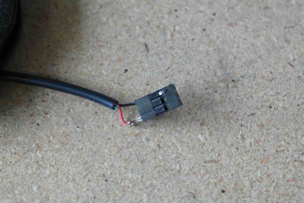
PS/2 differs from SPP in that its knowledge traces are additionally bidirectional. The standard aliases for the SPP mode are "Compatible", "Normal" or "Standard". Note There is a potentially better technique talked about on the boards (right here) which uses JST headers on the baseboard and both right-angled JST headers on the CS or simply regular proper-angled SIL headers. Please wait until someone has tried this methodology earlier than gluing to the panel. Put the PCB within the PT-10 case high where the panel would usually go, so the LEDs will be put in with out bending the leads. Place the panel on the PT-10 case, flip it over and see where it overlaps. This may make the panel sit flush with the PT-10 case top. The cables needs to be linked so the cable sits flat towards the top aspect of the CS PCB and the underside side of the base PCB, so the solder joints are on the inside of the bent cable. Do correct solder joints of all the pads. Be certain that you do not put cable in the extra "GND" pads Put all eight 8-wire cables in, plus the single 2-wire cable. Put the LEDs in the panel holes. If you are crazy and want to do illuminated knobs, Now's the time to solder wires between the LEDs on every rotary encoder.
댓글목록
등록된 댓글이 없습니다.